Letting software press the key fob
The alarm's radio hub is slow to wake, so a voice "disarm" can lag. The fix is to press the buttons on a spare enrolled key fob electronically — an ESP32 drives four isolated relays, each closing across one button, so Home Assistant and Google can Arm, Disarm, Part-arm and Panic. The fob keeps floating on its own power; nothing on its side ever touches the ESP32's ground.
How it works
Each relay is an electronic finger. A GPIO goes high, the relay's coil pulls in, and its contact closes across the two pads of one button — electrically identical to pressing it. The contact is a dry, isolated switch: it shares no copper with the coil or the ESP32, so it bridges the fob's button without dragging the fob's ground onto anything else. That isolation isn't a nicety here — as the note below explains, it's the whole reason this works.
Why a relay — and not an optocoupler or a transistor. This is the lesson that cost the most bench time. The fob floats: its button "common" sits behind a reverse-protection diode, not at true ground. Anything that shares a ground with the ESP32 — a common-ground opto board, or a bare transistor — bonds the fob's common to the system ground the moment it switches, and that jams the remote dead every time. We proved it twice before the penny dropped. A relay's contacts are galvanically isolated from its coil and the ESP32, so they bridge a button's two pads exactly like a fingertip, with nothing shared. Isolation here is the whole trick, not an optional extra.
Wire colour map
Two worlds that never meet. On the control side the colours are triggers and everything shares one ground. On the isolated fob side the same colour is that button's signal and one grey serves the shared common. Red and black are power only.
| From | Wire | To | Purpose |
|---|---|---|---|
| Control side — shares the ESP32 / 12 V ground | |||
| 12 V PSU + | red | Relay DC+ and buck input + | Coil power |
| 12 V PSU − | black | Relay DC− and buck input − | 0 V (= ESP32 GND) |
| Buck Type-C | USB-C | ESP32 USB-C port | 5 V for the ESP32 |
| ESP32 D23 | yellow | Relay IN1 | Arm trigger |
| ESP32 D22 | green | Relay IN2 | Disarm trigger |
| ESP32 D21 | blue | Relay IN3 | Part-arm trigger |
| ESP32 D19 | white | Relay IN4 | Panic trigger |
| ESP32 GND | black | Relay DC− | Logic ground (shared) |
| Isolated fob side — floats, touches nothing above | |||
| Relay COM1 | yellow | Arm button, signal pad | One side of the press |
| Relay COM2 | green | Disarm button, signal pad | One side of the press |
| Relay COM3 | blue | Part-arm button, signal pad | One side of the press |
| Relay COM4 | white | Panic button, signal pad | One side of the press |
| Relay NO1–4 | grey | The fob's shared common "G" pad | Other side of the press |
The one rule that makes or breaks it: the fob's grey "G" wires (relay NO) go only to the fob's own common pad — never to the 12 V −, the ESP32 GND, or the relay's DC−. The instant those grounds meet, the remote jams. Leave the fob on its own cell (or give it a completely separate, isolated 12 V supply) so its ground stays its own.
One channel, end to end
D23 high → IN1 → the coil pulls in → the contact closes COM-to-NO, bridging the Arm button's signal pad to the fob's common pad. That's exactly the short a continuity probe makes across those two points to press the button. The other three channels are identical, each with its own colour.
Where everything plugs in
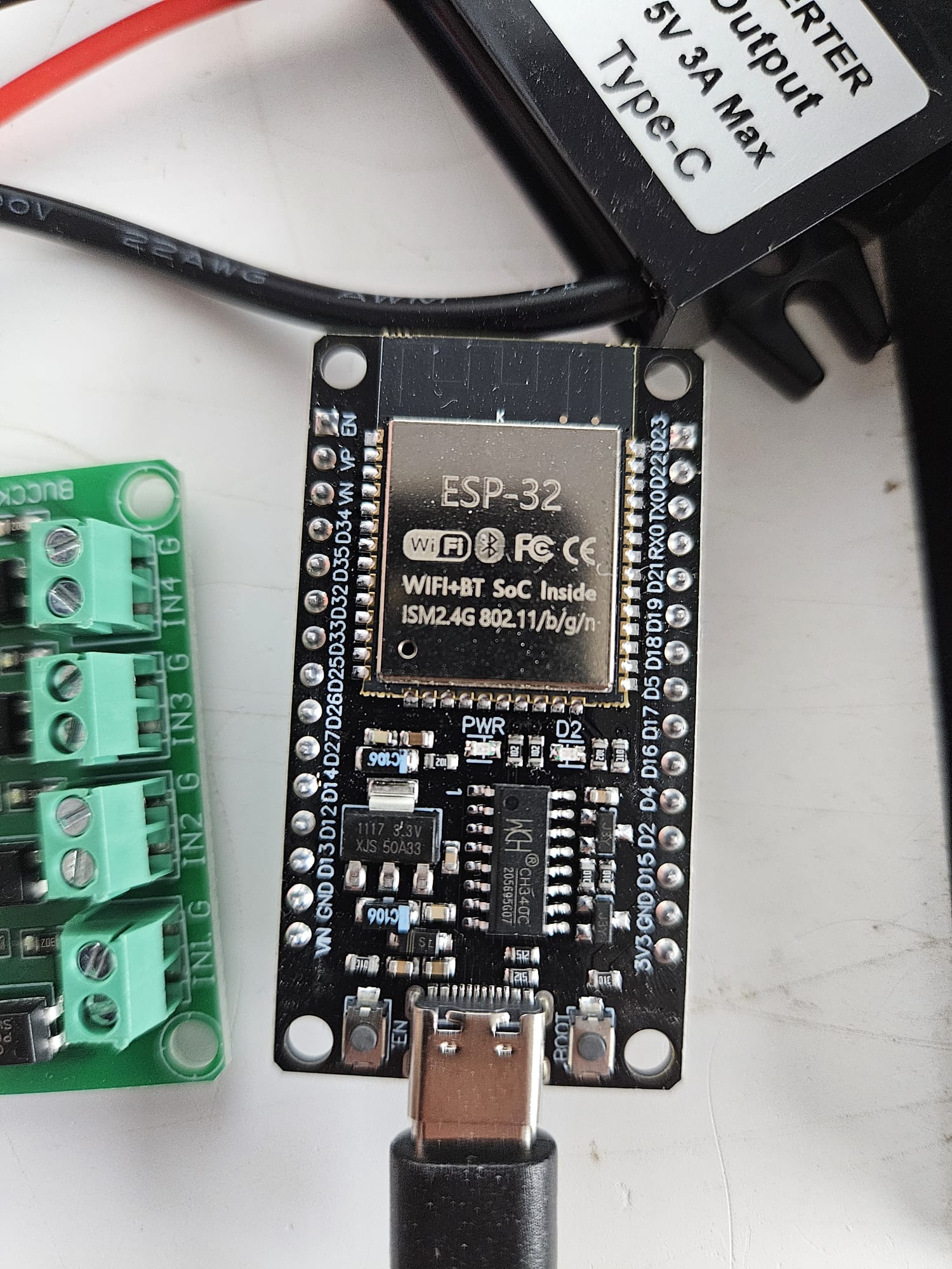
ESP32 · right-hand header
- D23 yellow → IN1 · Arm
- D22 green → IN2 · Disarm
- TX0/RX0skip — used for flashing
- D21 blue → IN3 · Part-arm
- D19 white → IN4 · Panic
- GND black → relay DC−
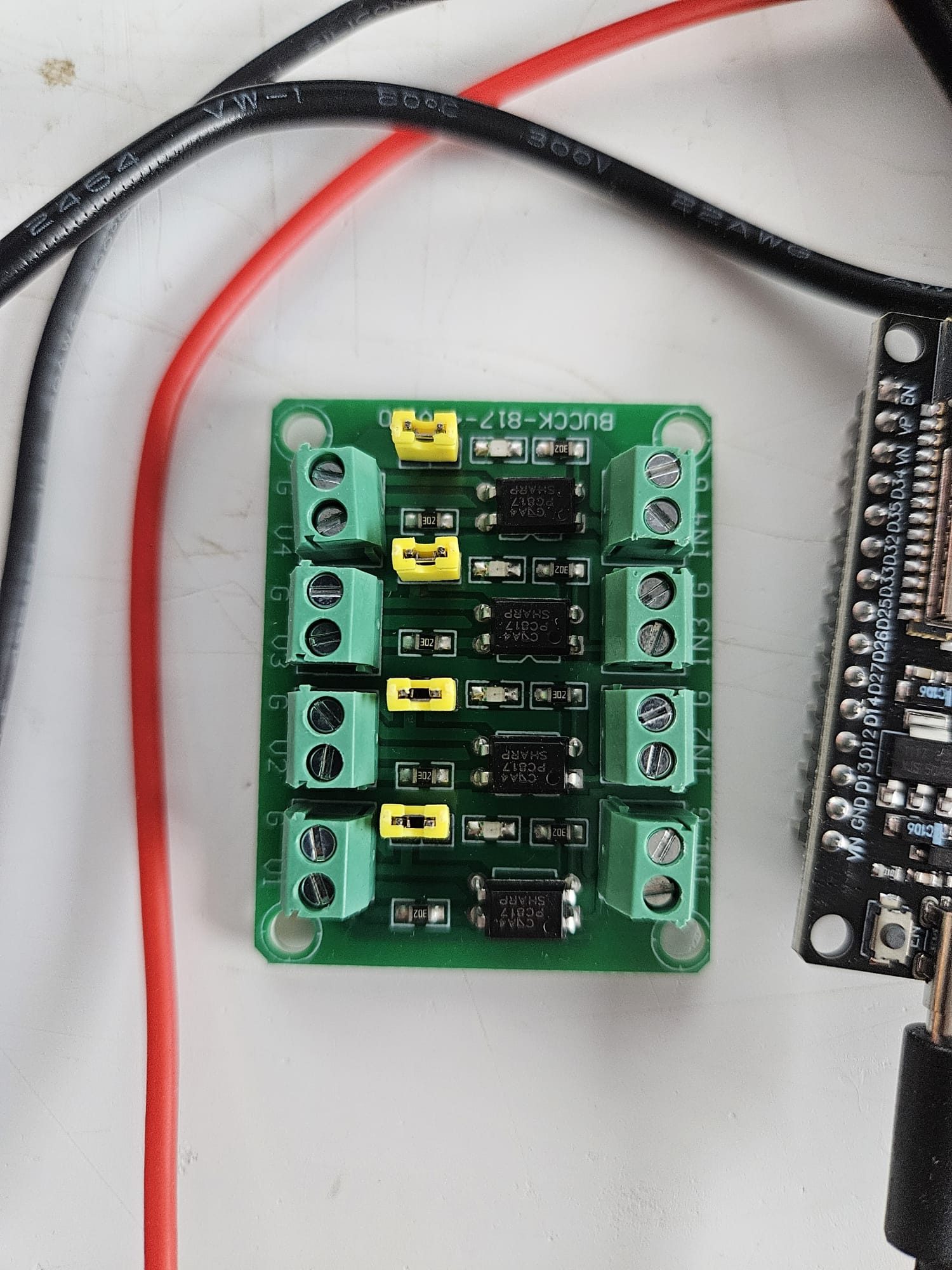
Relay module (4-ch, 12 V)
- DC+red → +12 V (coil power)
- DC−black → 0 V = ESP32 GND
- IN1-4colour in from D23/D22/D21/D19
- COMxthat button's signal pad (colour)
- NOxgrey → the shared common "G"
- jumperset High-level trigger (3.3 V high = on)
Remote PCB
- SW1Arm · top
- SW2Disarm
- SW3Part-arm
- SW4Panic · bottom
- presssignal pad → COM · shared common → NO
- powerown cell / isolated 12 V — ground stays apart
Your hardware, annotated
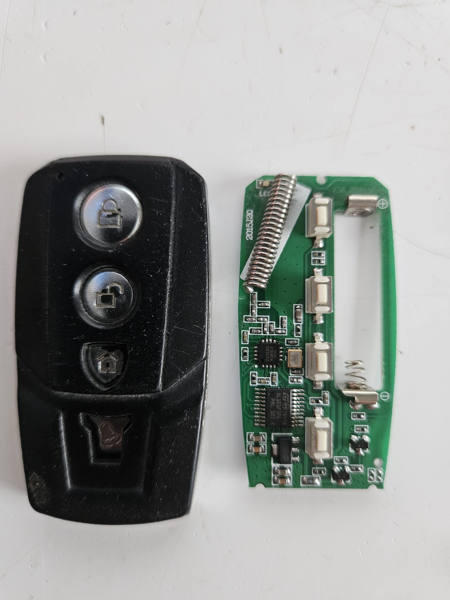
The two ends of the isolated side, drawn onto your own photos. Positions are close, but always confirm against the silkscreen and a continuity check before you commit a joint.
The road here
Build order
Set the relay board, then bench-test a click
Set the High/Low jumper to High-level trigger. Power DC+/DC− from 12 V, tie DC− to the ESP32 GND, and touch IN1 to 3V3 — the relay should click and a meter across COM–NO should close. Repeat for all four before anything goes near the fob.
Keep the fob floating
Leave the fob on its own cell (or a separate, isolated 12 V supply). Its ground must never bond to the ESP32/PSU ground — that single mistake is what jams it. Nothing you wire on the isolated side touches the control side's 0 V.
Find each button's two press points
For each button, identify the signal pad and the shared common "G" — a continuity probe across the two triggers that button. Those two points are the relay's COM and NO. On this remote the common sits behind a reverse-protection diode, which is exactly why it must stay isolated.
Wire the isolated side
Per channel: COMx → the signal pad in its function colour; NOx → the shared common with grey (one grey serves all four). Screw terminals, or short solder tails if you tap the pads directly. Keep joints small so the case still closes.
Wire the control side
DC+ → 12 V, DC− → 0 V. IN1←D23, IN2←D22, IN3←D21, IN4←D19, one black from ESP32 GND to DC−. Every colour is one clean trigger from a GPIO to an IN.
Power up in order
12 V to the relay DC+/DC− and to the buck. Meter the buck's USB-C output — confirm ~5 V — before plugging the ESP32. Then buck USB-C → ESP32.
Flash the firmware
Load the ESPHome config below over USB once, then adopt in Home Assistant — four button.alarm_remote_bridge_* entities appear. After that it's fully over-the-air.
Test each in a safe state
Press each button in HA where a stray Arm or Panic won't wake the street. You should hear the relay click, see the fob's own LED blink, and watch the alarm respond. Panic clicks about eight times over ~4 s — that's deliberate (see below).
Panic pulses, it doesn't hold. This fob self-terminates: hold a button and its transmit LED drops out on its own part-way through, so a single 3–4 s press wouldn't give the panel a sustained panic. Panic instead pulses the relay ~8 times over ~4 s, restarting the fob's transmission each time. Arm, Disarm and Part-arm are a single clean 600 ms press.
The real thing — ESPHome + Home Assistant
Local, no cloud. Four momentary button entities. Three drive their GPIO high for 600 ms then low; Panic repeats a short pulse ~8 times. They arrive in Home Assistant as button.alarm_remote_bridge_arm and friends, ready to wire to the alarm panel or expose to Google.
esphome:
  name: alarm-remote-bridge
  friendly_name: Alarm Remote Bridge
esp32:
  board: esp32dev
  framework: { type: arduino }

wifi:
  ssid: !secret wifi_ssid
  password: !secret wifi_password
  ap: {}                 # fallback hotspot for first setup
captive_portal:
logger:
api:                     # Home Assistant adds the encryption key
ota:
  - platform: esphome

# relay inputs, driven HIGH to close (board on High-level trigger).
# LOW at boot, so the ESP can never fire the alarm while it resets.
output:
  - { platform: gpio, id: out_arm,    pin: GPIO23 }
  - { platform: gpio, id: out_disarm, pin: GPIO22 }
  - { platform: gpio, id: out_part,   pin: GPIO21 }
  - { platform: gpio, id: out_panic,  pin: GPIO19 }

button:
  - platform: template
    name: Arm
    on_press: [ output.turn_on: out_arm,    delay: 600ms, output.turn_off: out_arm ]
  - platform: template
    name: Disarm
    on_press: [ output.turn_on: out_disarm, delay: 600ms, output.turn_off: out_disarm ]
  - platform: template
    name: Part-arm
    on_press: [ output.turn_on: out_part,   delay: 600ms, output.turn_off: out_part ]

  # Panic: pulse ~8× over ~4 s so a self-terminating fob keeps transmitting
  - platform: template
    name: Panic
    on_press:
      - repeat:
          count: 8
          then:
            - output.turn_on: out_panic
            - delay: 400ms
            - output.turn_off: out_panic
            - delay: 150ms
Flashing: add it in the ESPHome dashboard (or web.esphome.io for the first USB flash), put your Wi-Fi in secrets.yaml, install over USB once, then adopt it in Home Assistant — the four buttons appear automatically. After that it's fully over-the-air. D23/D22/D21/D19 are chosen deliberately: they sit low at boot, so the ESP32 can never ghost-press a button while it resets.
Think twice about voice disarm. Anyone your speaker can hear — including someone shouting through a letterbox — could say "disarm". Keep Disarm app- and dashboard-only, or require Google's PIN confirmation for it. Arm, Part-arm and Panic carry no such risk.
Sanity checklist before the first live press
- ✓ Fob left floating — its ground touches nothing on the ESP32/PSU side
- ✓ Relay board on High-level trigger; every channel clicks on the bench
- ✓ COM → signal pad, NO → the shared common "G"
- ✓ DC+ = 12 V, DC− = ESP32 GND; buck 5 V metered before the ESP32
- ✓ Each trigger is one colour GPIO → INx; each press is COMx → NOx
- ✓ Alarm in a safe state for the first live press